The case
The printed case for the bench link board, with the cradle in its bay for a bare Dabao or a socket guide for a Dabao with pin headers, and how it goes together.
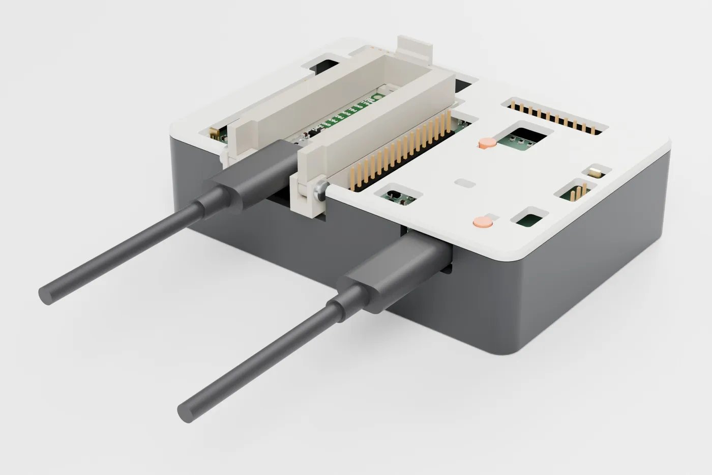
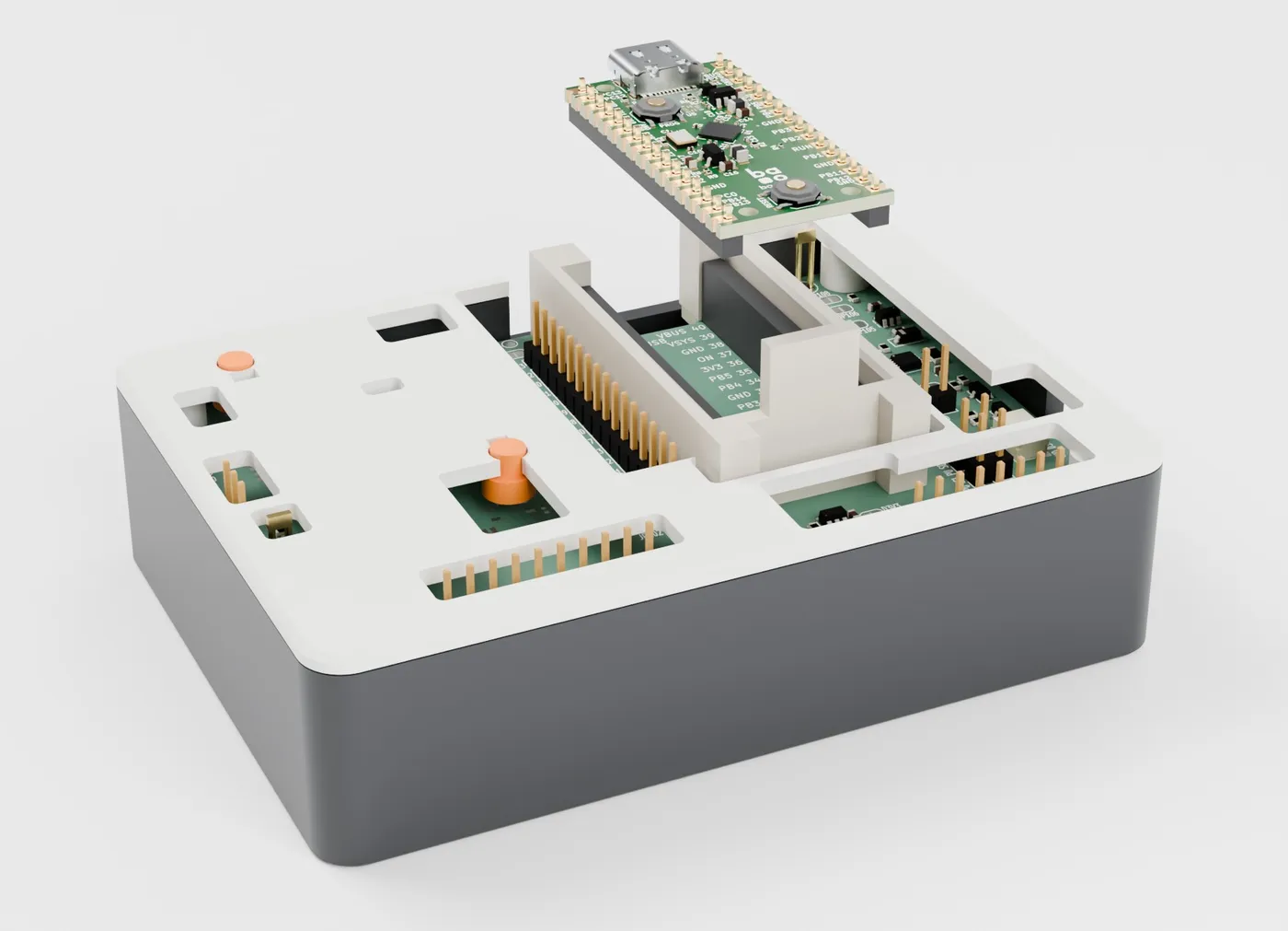
The board is built one of two ways: Probes, for a bare Dabao with no headers on 32 spring probes, and Sockets, for a Dabao with pin headers in two 1x16 sockets. One printed case fits both, with an open bay in its middle:
- for Probes, the cradle that holds the Dabao down on the probes stands in the bay;
- for Sockets, a socket guide stands in the bay in the cradle’s place.
The files, print settings and screws are on Printing the parts yourself.
Base, deck and plungers
The case is 101 x 72 x 26.1 mm. It has four printed parts: a base the board sits in, a deck that covers the board from above, and two plungers for the BOOT and RST buttons.
The board rests on four bosses of the base, at its four M3 holes. Four posts under the deck stand on the board at the same holes, each with a heat-set insert. Four M3 x 20 screws come up from below, through the bosses and the board, into the inserts. The board is clamped between boss and post, and no screw shows on top. The base’s walls stop 0.2 mm under the deck, so the board alone sets the stack and the seam is a shadow line all round.
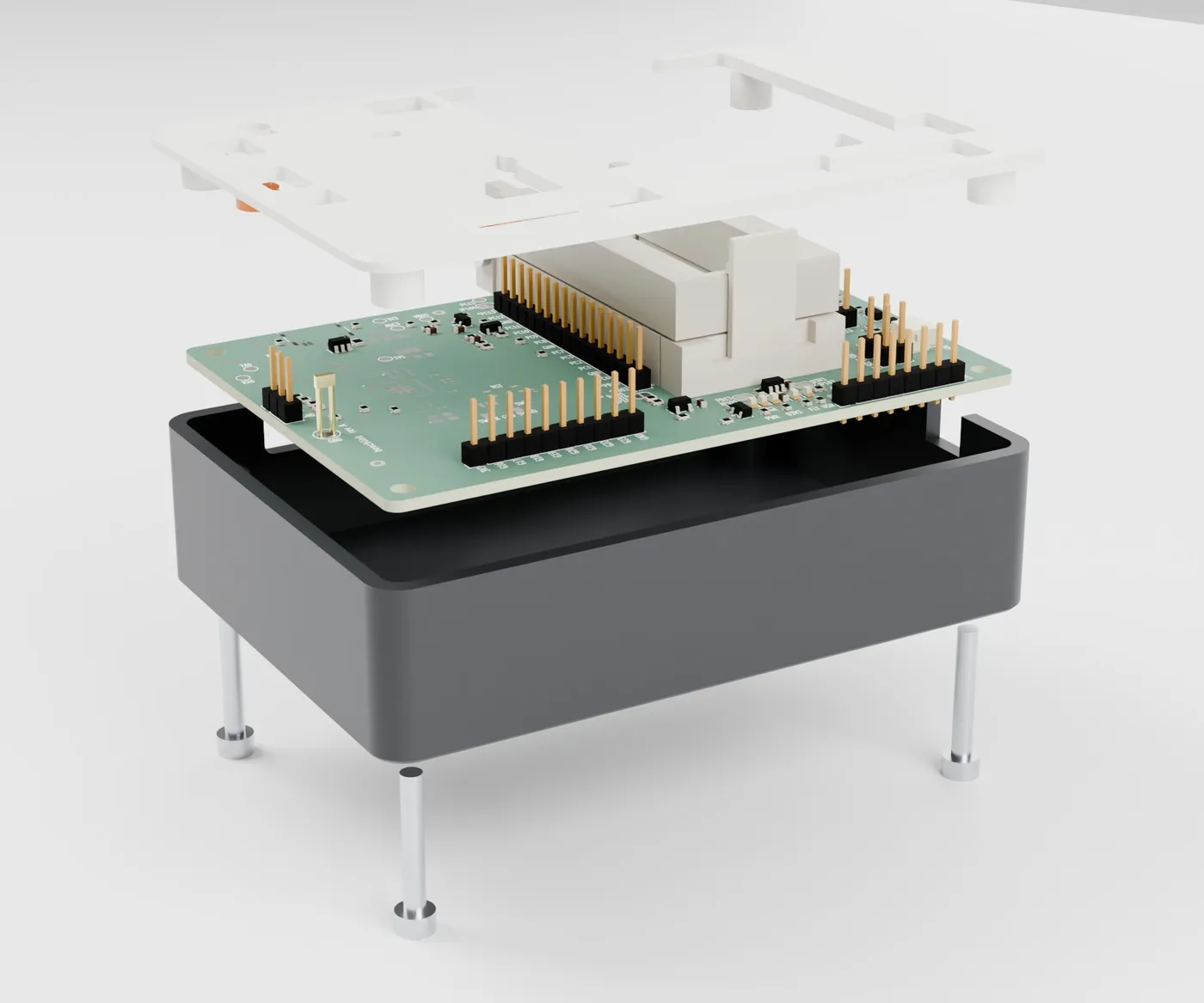
The cradle’s bay
The middle of the deck is open from the front wall to behind the breakout headers. The bay holds the cradle, both breakout headers with jumper housings on every pin, their pin labels, and the test points and GND loop beside them.
At the front, the bay goes out through the wall, 31 mm wide. The cradle’s hinge stands in it, its lid swings out through it to its stop, and the Dabao’s USB-C plug comes out of it.
The deck’s top is 7.6 mm above the board, level with the top of the cradle’s frame (7.3 mm). The cradle needs no legs in the case: the floor is 1.6 mm below the ends of the probe sleeves.
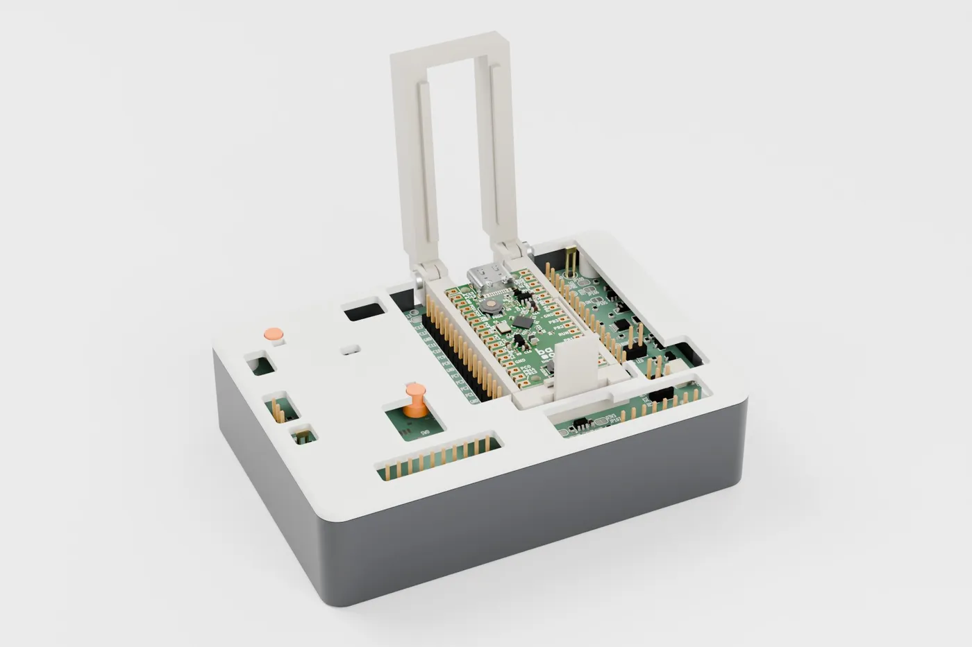
Openings
- Connectors and test points. Every other connector and test point has an opening in the deck, wide enough to show its labels on the board. Jumper housings go down onto the headers. A probe tip 1 mm thick goes straight down onto every test pad.
- LEDs. The five LEDs (
PWR,ACT,D3V3,FLT,USR) can be seen up to 30° from straight above, from every side. - Buttons.
BOOTandRSTeach have a plunger: a 4.0 mm stem in a 4.4 mm hole of the deck, on a 6.0 mm flange that rests on the switch. The flange keeps it in the case. The stem stands 0.5 mm above the deck. A slot beside each hole shows the button’s label. - Plugs. The board’s USB-C plug goes in through a window in the front wall, sized for the largest plug the USB Type-C specification allows. The I2C connector’s plug goes in through a window in the right wall. The SWD connector’s plug lies on the board under its opening, and its cable leaves upwards.
The socket guide, for Sockets
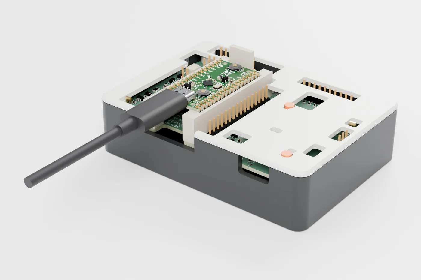
The Sockets build uses the same base, deck and plungers. The cradle is not fitted. In its place, a printed socket guide is screwed to the Dabao site’s four holes with four M2.5 x 6 screws from below, as the cradle’s frame is.
The two sockets are Samtec SSW-116-21-G-S, 8.38 mm high. With standard 2.54 mm pin headers on the Dabao (a 2.5 mm spacer), the Dabao’s underside stands 10.88 mm above the board and its top 12.48 mm, above the deck’s top (7.6 mm). Its buttons and USB-C stay in reach, and it is plugged in and pulled out straight up with the case closed.
The guide has three features:
- Walls round the Dabao’s outline, 0.25 mm from it, up to 0.5 mm above its underside, with a 0.6 mm lead-in. They bring the headers’ pins over the sockets. The Dabao’s edges stand 1.1 mm above the walls, to be held.
- Front stops on either side of the notch at the USB-C end. The USB-C receptacle and its plug stay clear.
- A key, 11 mm wide and 20 mm high, behind the far end. A Dabao turned 180° would put its 5 V pin on a GPIO net. Turned that way, its USB-C receptacle, 1.16 mm past its edge, is at the far end: it lands on the key with its pins’ tips 1.5 mm above the sockets, and goes no further.
The model check holds the guide, the sockets, the headers and the Dabao against the board, its parts, the jumper housings, the base and the deck, and the Dabao’s USB-C plug at its largest.
Putting it together
- Press the four inserts into the deck’s posts, flush with the posts’ ends.
- Probes: fit the cradle to the board, and leave its lid closed. Sockets: screw the socket guide to the site’s four holes from below.
- Lay the board in the base, its USB-C receptacle at the front window.
- Drop the two plungers, stem up, onto
BOOTandRST. - Lower the deck over the board: the stems go into their holes, the posts onto the board’s holes, the cradle or the guide into the bay.
- Turn the case over, holding the deck on, and screw the four M3 x 20 up into the inserts until the board is held. Do not crush it.